
What 2D vision tells a robot
A 2D machine-vision system captures an image and locates features in pixel coordinates. Software can identify a part, measure it, read a code, inspect a surface or estimate an in-plane position and rotation. A robot guidance application converts the vision result into a pose the robot can use.
A conventional 2D camera does not directly measure height. The application is often easiest when parts lie on a known plane and vary mainly in X, Y and rotation around the vertical axis. If height, tilt or overlapping geometry changes, the system may need a 3D sensor, another measurement method or a more constrained presentation.
- Part presence, position and in-plane rotation
- Inspection, measurement, identification and code reading
- Fixed-camera or robot-mounted camera arrangement
Lighting and calibration matter as much as the camera
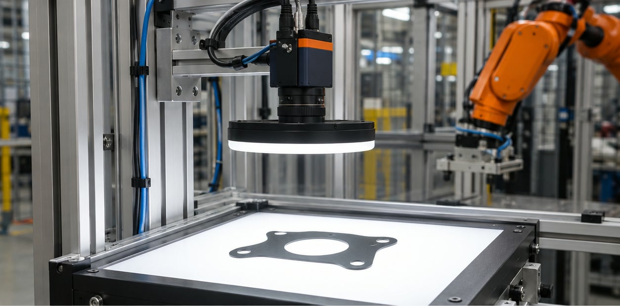
Image quality depends on the lens, field of view, resolution, working distance, exposure and lighting. Glare, shadows, reflections and changing ambient light can hide features even when the camera has enough pixels. Test the variation in actual parts and production conditions.
The camera reports image coordinates, while the robot works in its own coordinate system. Calibration establishes the mapping between them. In robot guidance, hand-eye calibration also accounts for the relationship between the camera and robot, whether the camera is fixed or mounted on the arm.
- Choose a lens, resolution and field of view for the smallest feature to detect
- Control illumination and assess glare, shadows, reflections and surface changes
- Calibrate camera-to-world or camera-to-robot coordinates after mounting
Design the result and handshake with the robot
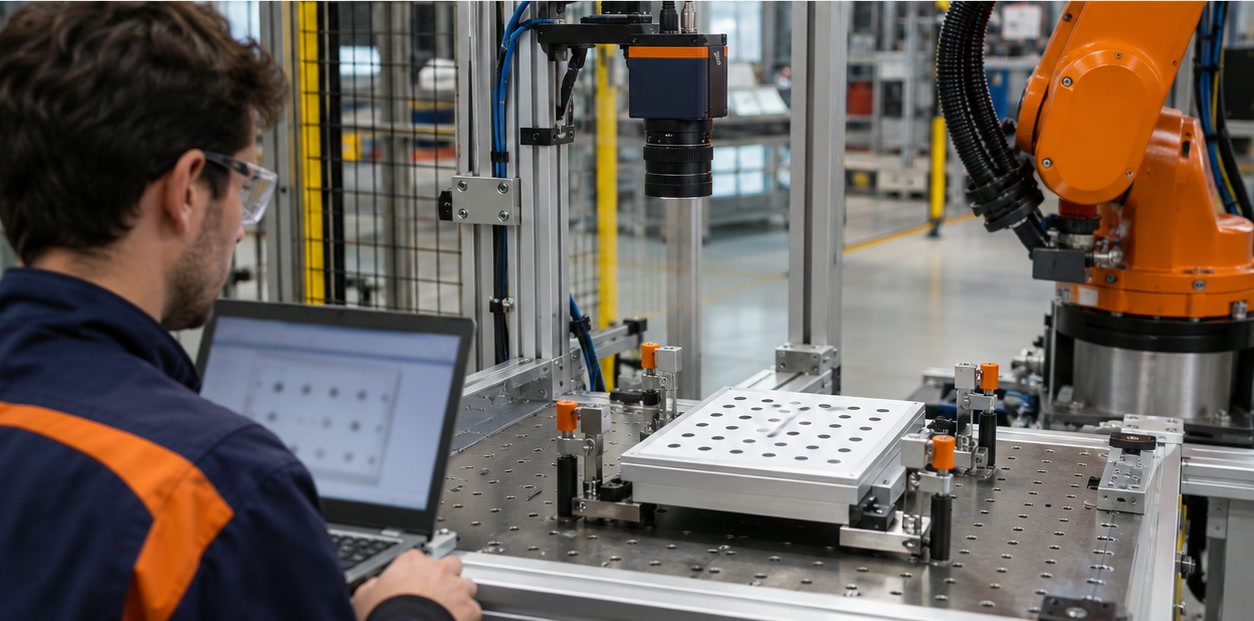
The vision system should return the information the robot actually needs: a part pose, quality decision, ID or a clear no-result status. Define how the controller triggers an image, receives the result, handles timeouts and responds to a missing or rejected part.
Run calibration and validation after final mechanical mounting. Check multiple positions across the field of view, part variants, cycle time, communication faults and recovery. Recalibrate after a camera, lens, fixture or robot mounting change that affects the established coordinate relationship.
- Trigger, result format, timeout and error-handling signals
- Robot tool centre point and coordinate-frame conventions
- Validation across the working area and after any relevant mechanical change
Can a 2D camera guide a robot to pick a part?
Yes, when the application can use a calibrated mapping from image coordinates to the robot coordinate system. A 2D setup is commonly suited to parts presented on a known plane with limited height variation.
Does 2D machine vision measure object height?
A conventional 2D image does not directly provide height. Applications with significant height, tilt or overlapping geometry may require 3D sensing or another method.
Sources and further reading
- Cognex — 2D transformations for machine vision — Explains mapping image pixel coordinates into a robot coordinate system.
- Cognex — Vision-guided pick or place workflow — Example workflow for locating a part and returning pose data to a robot.
- Cognex — Hand-eye calibration — Explains camera-to-robot calibration for fixed and robot-mounted cameras.
Technical descriptions link to published sources. Specifications can change; verify the current documentation before purchase.