
A vision-guided cell links several systems
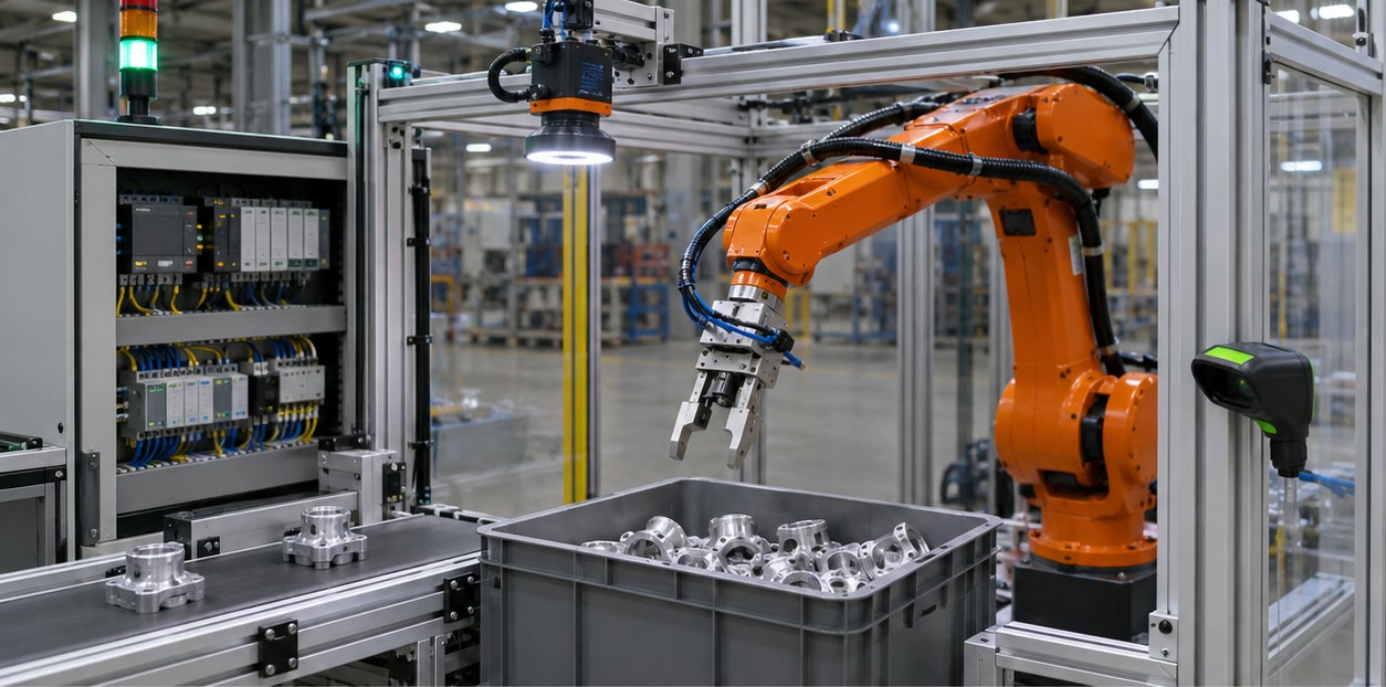
A vision-guided robot picking cell combines a robot, camera, image-processing software, part presentation, end effector, controller and safety system. The camera detects a target; software estimates its position; calibration maps that result into the robot’s coordinate frame; the robot moves the tool to pick the part.
Part presentation is a design input, not a detail to solve after camera selection. A tray, conveyor or bin changes how parts overlap, what surfaces are visible and which grasp approaches are available.
- Robot and controller with a defined tool centre point
- Camera, optics, lighting and vision job
- Gripper or vacuum tool, part presentation and fixtures
- Safety devices, I/O, network and upstream/downstream equipment
Define the data and motion handshake
The cell needs a clear sequence for requesting an image, receiving a result and deciding what to do next. Define the result fields, coordinate frame, timestamp, part identifier, confidence or validity status, communication timeout and behavior when no pick target is returned.
The robot program should distinguish a valid pick pose from a stale or incomplete result. It also needs logic for grip confirmation, part release, rejected picks, recovery and safe restart.
- Image trigger and exposure timing
- Robot-coordinate pose, part ID and result-validity signal
- Timeout, no-part, failed-grip and recovery states
Validate the whole application in production conditions
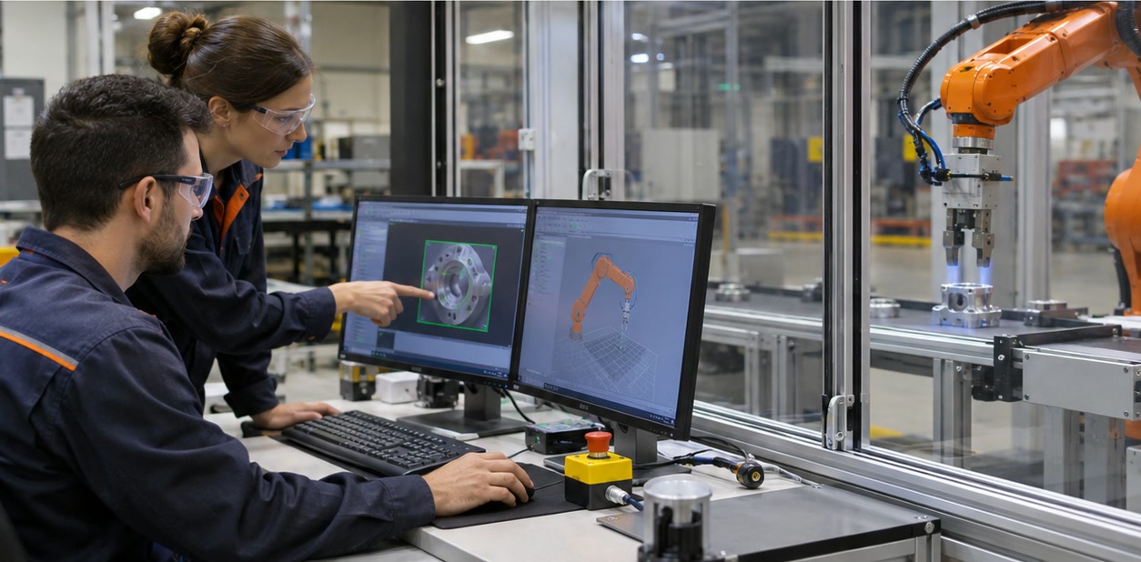
Calibration and vision detection are only parts of the outcome. Test camera coverage, robot reach, tool collision clearance, grip stability, cycle time, part variation and safety behavior in the intended workcell. Include the highest and lowest bin fill, representative surfaces and normal shifts in lighting or ambient conditions.
After commissioning, document the calibration, robot and vision backups, camera mounting, approved part families and maintenance steps. Recheck the system after a relevant mechanical or software change.
- Representative parts, poses, variants and environmental conditions
- Successful-pick and cycle-time measures with agreed sampling
- Calibration record, backups, change control and fault-recovery instructions
What equipment is needed for a vision-guided robot picking cell?
A typical cell includes a robot and controller, vision camera and optics, lighting, processing software, an end effector, part presentation, fixtures or conveyors, communication interfaces and required safety equipment.
Does the vision system move the robot directly?
Usually the vision system returns a measured target pose or offset. The robot controller applies the calibrated coordinate transform and executes the programmed motion and process logic.
Sources and further reading
- Cognex — Vision-guided pick or place workflow — Example workflow from image acquisition and feature detection to robot alignment.
- Cognex — Hand-eye calibration — Camera-to-robot calibration considerations for fixed and robot-mounted cameras.
- Festo — Robot gripper selection in five steps — Application factors for selecting and validating a robot gripping concept.
Technical descriptions link to published sources. Specifications can change; verify the current documentation before purchase.