
A 3D vision system estimates depth and object pose
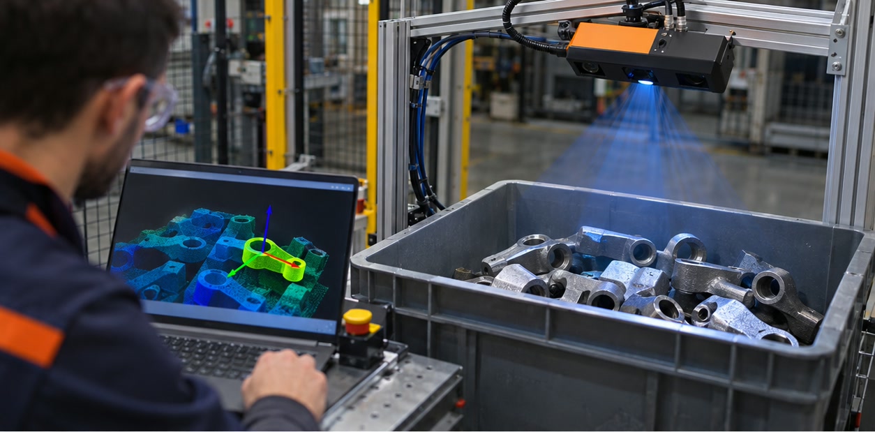
A 3D machine-vision system captures depth information as well as image features. Depending on the sensor, it may build a point cloud or depth map that represents the visible surfaces of parts. Software can use these data to locate an object, estimate its orientation and return a pick pose to the robot.
Industrial 3D sensors use different optical principles, such as laser triangulation, structured light or stereo vision. Each design has limits involving field of view, working distance, scan speed, surface reflectivity, occlusion and measurement range. Choose a sensor for the parts and cycle, then test the difficult surfaces and orientations.
- Depth or point-cloud data for three-dimensional shape
- Object detection and pose estimation for a robot target
- Sensor choice depends on geometry, surfaces, field of view and cycle time
Plan the camera view and robot reach together
A camera cannot find a surface it cannot see. The sensor must view enough useful geometry to estimate a stable pose, while the robot needs a collision-free path to reach the part and the gripper needs a usable contact point. Bin walls, overlapping parts, shiny surfaces and dark or transparent materials can create incomplete or noisy measurements.
The camera may be fixed above a work area or mounted on the robot. A fixed camera can cover a stable work zone; a robot-mounted sensor can change viewpoint, but adds motion, cabling and calibration considerations. The application layout should account for the sensor’s view and the robot’s full tool envelope.
- Visible surfaces and occlusion across likely part orientations
- Camera mounting, lighting, working distance and field of view
- Robot reach, collision clearance, gripper access and cable routing
Calibrate and validate the pose transfer
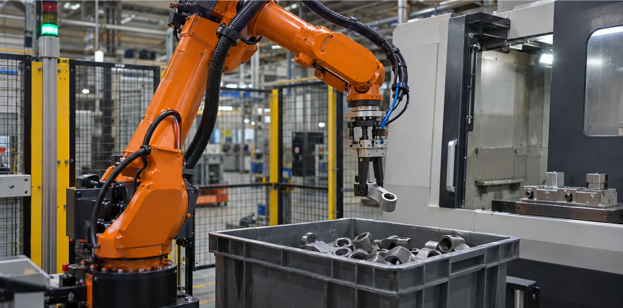
The vision system and robot use different coordinate frames. Calibration establishes how a point or pose measured by the camera maps into the robot’s coordinates. For a robot-mounted camera, hand-eye calibration is needed to connect the camera frame to the robot; a fixed-camera arrangement needs a calibrated relationship to the work area.
Validate the complete pick with representative bins, parts, surface conditions and fill levels. Measure not only pose-estimation repeatability but also successful grasp rate, cycle time, recovery behavior and the effect of changing parts or moving the sensor.
- Camera-to-robot calibration and robot tool centre point
- Pose quality checks and rejection behavior for low-confidence results
- Trials across bin fill, part orientation, surface and lighting variations
What does a 3D vision system provide to a picking robot?
It can provide depth information and an estimated object pose in the camera’s coordinate frame. After calibration and application processing, the robot can use the pose as a pick target.
Why can a 3D robot-picking system miss parts in a bin?
Occlusion, reflective or transparent surfaces, incomplete depth data, poor viewing geometry, calibration error, unsuitable gripper access or invalid robot coordinates can all affect a pick. Test representative parts and bin conditions to find the limiting factor.
Sources and further reading
- Cognex — Operation of a 3D triangulation sensor — Explains how a laser profile is captured and assembled into 3D data.
- Cognex — Hand-eye calibration for vision-guided robotics — Describes establishing the spatial relationship between a vision system and a robot.
- Mech-Mind — Mech-Eye industrial 3D cameras — Manufacturer overview of industrial 3D camera categories and applications.
Technical descriptions link to published sources. Specifications can change; verify the current documentation before purchase.