
A pneumatic gripper turns air pressure into jaw motion
A pneumatic gripper uses compressed air to move jaws or fingers. Many parallel models use an internal piston and linkage to open or close two jaws; other designs use angular, three-finger or adaptive motion. The tool may be single-acting with a return spring or double-acting with air used in both directions.
The manufacturer’s force and stroke figures depend on pressure, jaw position and the gripper design. Force at the jaws is not the same as the maximum part mass the tool can safely hold during robot motion.
- Parallel, angular, three-finger and adaptive arrangements
- External or internal gripping, depending on jaw and part design
- Single-acting or double-acting actuation
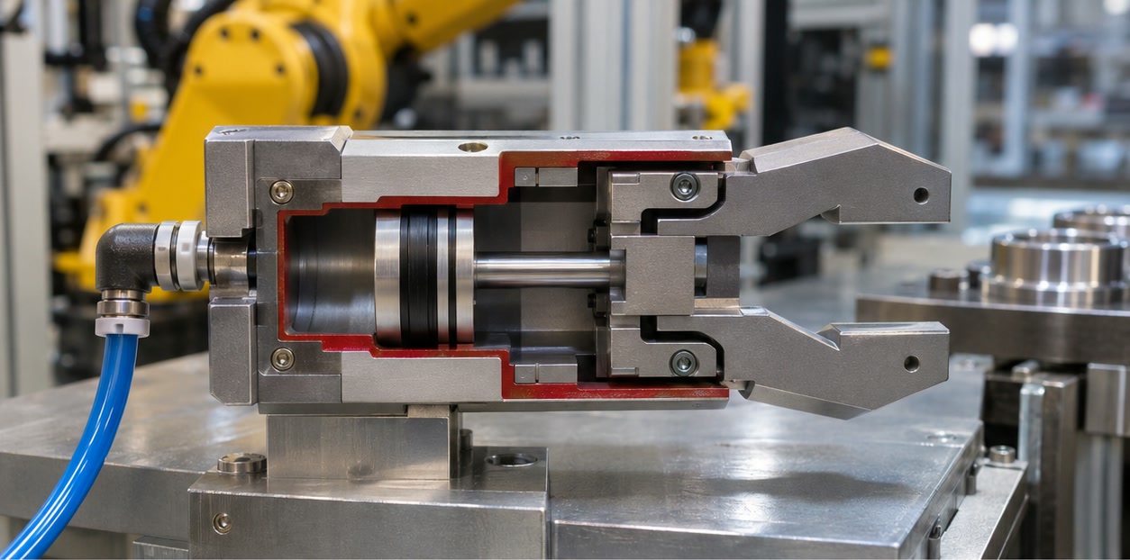
Size the gripper for the part and cycle
Select jaw travel for the full part tolerance range, then size the gripping force for the part mass, friction, orientation and robot acceleration. Longer fingers create additional leverage and can reduce the available force at the contact point, so compare the manufacturer’s allowable finger length and moment limits.
Use a representative part trial to check grip stability, part marks, repeatability, closing time and release. Design for the fastest expected motion and include how the system will detect an empty grip or an incorrectly seated part.
- Required stroke and gripping range
- Force at the specified operating pressure and jaw position
- Finger length, workpiece inertia, acceleration and sensor position
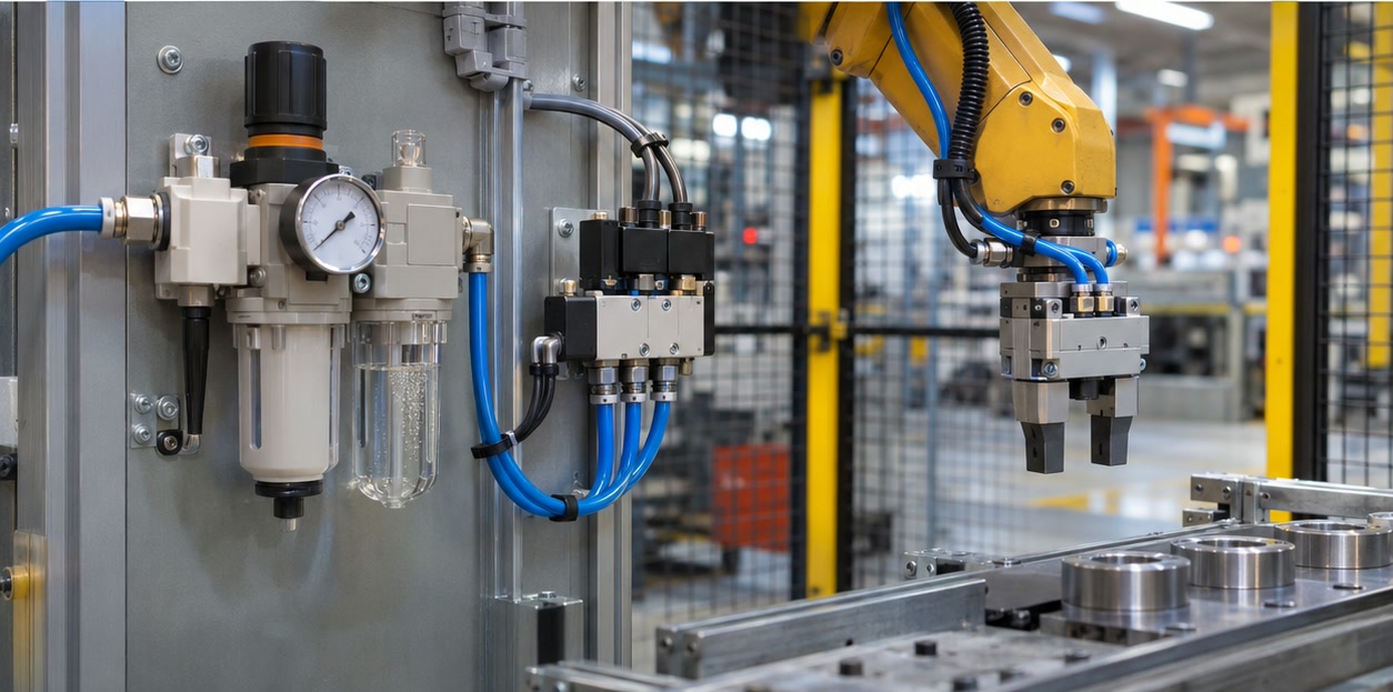
Plan for air quality, routing and failure behavior
The gripper depends on a suitable compressed-air supply, tubing and valves. Check operating pressure, air quality, flow, fittings and pressure drop through the tool and robot dress pack. A pressure loss or hose failure can change the grip state; determine whether a spring, check valve or other retention method is required for the application.
Specify the open/closed or part-present sensors and how their signals reach the robot controller. Include maintenance access, seal replacement, spare fingers and a safe method to isolate and exhaust air before service.
- Pressure and air quality required by the selected model
- Hose routing, valve location, flow, leakage and robot wrist connections
- Grip sensing, loss-of-pressure response and service isolation
What does double-acting mean on a pneumatic gripper?
Compressed air is used to drive the gripper in both opening and closing directions. A single-acting design uses air in one direction and a spring or another mechanism for its return.
How do I calculate the force needed for a pneumatic robot gripper?
Start from the workpiece mass, orientation, acceleration, friction and jaw geometry, then use the manufacturer’s force data at the actual pressure and jaw position. Validate the result with representative parts and the intended robot motion.
Sources and further reading
- Festo — Gripper product categories — Product overview and definitions for pneumatic gripping force.
- Festo — Selected product catalogue — Manufacturer catalogue with electric and pneumatic gripper examples and specification fields.
Technical descriptions link to published sources. Specifications can change; verify the current documentation before purchase.